Noillek
Membre
-
Inscription
-
Dernière visite
-
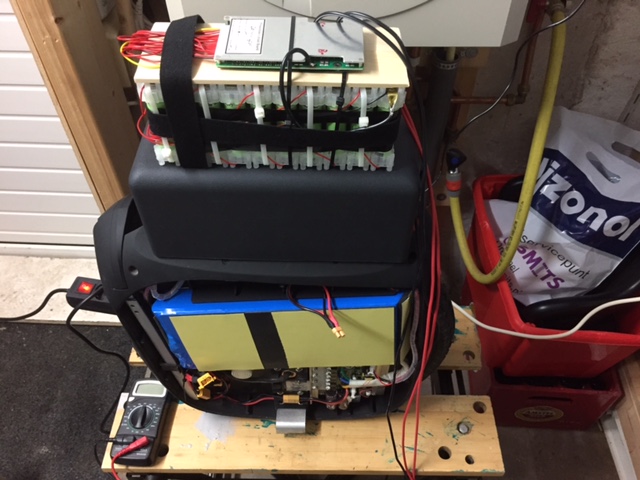
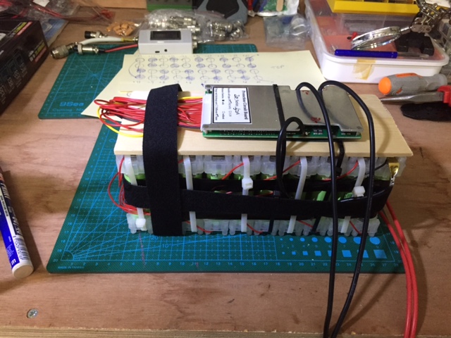
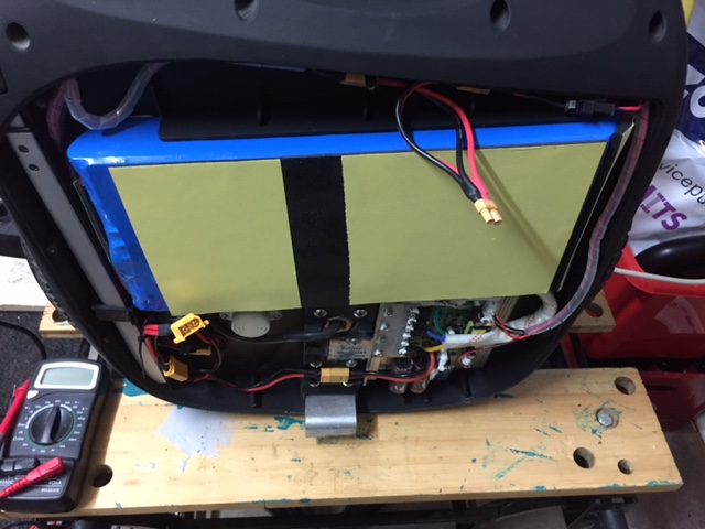
Yesterday night assembled everything... here is some pictures. 1) Battery pack was a struggle to get all cells connected with this Vruzend Kit... next one i will definitely try welding instead, BMS was pretty straight forward and easy to connect all the cables. 2) Parallel cables created to be able to easily plug the extra Battery, top connector is a XT30 for charging circuit and the bottom one is a XT60 for output for the PCB, only had 14 AWG cable so i used for everything. 3) Created as well an adapter to charge the battery extra pack separately from the original batteries, only needed if the pack is not connected to the wheel, so it minimizes the risk of sparks and fireworks.Charging so i can have same tension and connect all cables safely. 4) Last part was to get all cables connected and make sure that i have tension everywhere. Next challenge is to secure well and nicely the extra pack, ideally allowing me to still use the seat... more to come on this one. Before i will still take it for a test drive even if ugly
.jpg.18c63c461ad681b638ccefbd4da810e2.jpg)

-
Thanks Hansolo, i guess that i will do the same, since from the moment i connect in parallel with the charging port, is the same from the output port from the BMS so i guess that will balance each other battery packs.
-
Hi all, Since I meet some of you when you came to Amsterdam, i decided to create an extra battery pack for my Msuper, havent rest until i learned and gather all the material needed to create my battery pack (20S2P) same as original batteries so I'm adding more 418 Wh to my original batteries. I'm struggling to understand why the original batteries have a connection 4 wires in parallel with each battery side. I got the connections for the charger and the ones that go to the Control board to power the wheel... still don't know what is the purpose of the additional 4 wires that connect each side of the original batteries. Does anyone can help me on solving this mystery? See below my current configuration. I'm using 40 Cells Panasonic 2900mah in a 20S2P configuration and a generic BMS for 72v/84v 50A. Also know the cable types 22 AWG for the mysterious 4 wires 20 AWG for the charging wires also 16 AWG for the Output for the PCB/Motor and then the final cable connected to the PCB is 14 AWG. Thank you p.s. - sorry for not write in French, feel free to reply in French as i'm using google translate to be able to follow the forum topics. Merci
-
Merci beaucoup
-
Hi all, I'm Pedro a Portuguese living in the Netherlands, and like you a Electric Unicycle enthusiast, meet some of you when the Paris Group did the trip from Paris to Amsterdam and got even more excited about EUC after seeing that you too this activity to an all different level. I have a Gotway MSuper V3S and a Inmotion V8. Looking forward to learn more from you and hopefully meet soon. Sorry for writing in English Regards, Pedro